

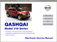
Мультимедийное руководство на английском языке по техническому обслуживанию и ремонту автомобиля Nissan Qashqai серии J10 с 2006 года выпуска.
- Автор: –
- Издательство: Nissan
- Год издания: 2007
- Страниц: –
- Формат: –
- Размер: 332,9 Mb
Руководство на английском языке по техническому обслуживанию и ремонту автомобиля Nissan Qashqai серии J11 2015 года выпуска.
- Автор: –
- Издательство: Nissan International
- Год издания: 2014
- Страниц: –
- Формат: PDF
- Размер: 193,7 Mb
Мультимедийное руководство на английском языке по техническому обслуживанию и ремонту автомобиля Nissan Qashqai серии J10.
- Автор: –
- Издательство: Nissan
- Год издания: –
- Страниц: –
- Формат: NRG
- Размер: 112,6 Mb
Руководство по эксплуатации и техническому обслуживанию автомобиля Nissan Qashqai первого поколения.
- Автор: –
- Издательство: Nissan Europe
- Год издания: 2007
- Страниц: –
- Формат: PDF
- Размер: 12,8 Mb
Руководство по техническому обслуживанию и ремонту автомобиля Nissan Qashqai с 2007 года выпуска с бензиновыми двигателями объемом 1,6/2,0 л.
- Автор: –
- Издательство: МодЭкс плюс
- Год издания: –
- Страниц: 366
- Формат: –
- Размер: –
Руководство по эксплуатации, техническому обслуживанию и ремонту автомобилей Nissan Qashqai с 2007 и Nissan Qashqai + 2 с 2008 года выпуска с бензиновыми двигателями объемом 1,6/2,0 л
- Автор: –
- Издательство: Третий Рим
- Год издания: 2011
- Страниц: 386
- Формат: PDF
- Размер: 66,7 Mb
Руководство по эксплуатации и ремонту автомобиля Nissan Qashqai + 2 с 2008 года выпуска с бензиновыми и дизельными двигателями.
- Автор: –
- Издательство: Монолит
- Год издания: –
- Страниц: 466
- Формат: –
- Размер: –
Руководство по эксплуатации и ремонту автомобиля Nissan Qashqai с 2014 года выпуска с бензиновыми и дизельными двигателями
- Автор: –
- Издательство: Монолит
- Год издания: –
- Страниц: 526
- Формат: –
- Размер: –
Руководство по эксплуатации и ремонту автомобиля Nissan Qashqai с 2014 года выпуска с бензиновыми и дизельными двигателями
- Автор: –
- Издательство: Монолит
- Год издания: –
- Страниц: 526
- Формат: –
- Размер: –

Руководство по эксплуатации и техническому обслуживанию автомобиля Nissan Qashqai 2007-2013 годов выпуска.
- Автор: –
- Издательство: MoToR
- Год издания: –
- Страниц: 296
- Формат: –
- Размер: –
Руководство по эксплуатации, техническому обслуживанию и ремонту автомобиля Nissan Qashqai серии J10 с 2007 года выпуска с бензиновыми двигателями.
- Автор: –
- Издательство: Автонавигатор
- Год издания: 2008
- Страниц: 560
- Формат: –
- Размер: –
Руководство по эксплуатации, техническому обслуживанию и ремонту автомобиля Nissan Qashqai серии J10 с 2007 года выпуска с бензиновыми двигателями.
- Автор: –
- Издательство: Автонавигатор
- Год издания: 2008
- Страниц: 560
- Формат: PDF
- Размер: 127,0 Mb
Руководство по эксплуатации, техническому обслуживанию и ремонту автомобиля Nissan Qashqai серии J10 2007-2014 годов выпуска с бензиновыми двигателями моделей HR16DE и MR20DE.
- Автор: –
- Издательство: Автонавигатор
- Год издания: –
- Страниц: 560
- Формат: –
- Размер: –
Руководство по эксплуатации, техническому обслуживанию и ремонту автомобиля Nissan Qashqai с 2013 года выпуска с бензиновыми двигателями.
- Автор: –
- Издательство: Автонавигатор
- Год издания: –
- Страниц: 568
- Формат: –
- Размер: –
Руководство по техническому обслуживанию и ремонту автомобилей Nissan Qashqai и Nissan Qashqai + 2 серии J10 с 2008 года выпуска с бензиновыми двигателями объемом 1,6/2,0 л.
- Автор: –
- Издательство: Автонавигатор
- Год издания: –
- Страниц: 592
- Формат: –
- Размер: –
Руководство по техническому обслуживанию и ремонту автомобилей Nissan Qashqai и Nissan Qashqai + 2 серии J10 с 2008 года выпуска с бензиновыми двигателями моделей HR16DE и HR20DE.
- Автор: –
- Издательство: Автонавигатор
- Год издания: –
- Страниц: 360
- Формат: –
- Размер: –
Руководство по эксплуатации, техническому обслуживанию и ремонту автомобиля Nissan Qashqai с 2014 года выпуска с двигателями объемом 1,2/1,6/2,0 л.
- Автор: –
- Издательство: Мир автокниг
- Год издания: –
- Страниц: 334
- Формат: –
- Размер: –
Руководство по эксплуатации, техническому обслуживанию и ремонту автомобиля Nissan Qashqai с 2014 года выпуска с двигателями объемом 1,2/1,6/2,0 л.
- Автор: –
- Издательство: Мир автокниг
- Год издания: –
- Страниц: 335
- Формат: –
- Размер: –

Nissan Qashqai 2007 – 2015: repair manual and repair manual for maintenance, wiring diagrams, owners manual – free download.
Guidelines for repair, operation and maintenance, the device cars Nissan Qashqai model J10 from 2008 release, with petrol engines HR16DE, MR20DE.
Nissan Qashqai repair manual contains:
- detailed instructions for maintenance,
- diagnostics,
- repair and adjustment of engines,
- engine management systems,
- camshaft control systems,
- braking systems (including ABS, ESP, ESP, TCS anti-skid system and EBD brake force distribution) etc.
Details are presented self-diagnostic procedures and fault codes of engine management systems, CVT, ABS and other vehicle systems. Information available in the Nissan Qashqai repair manual will allow car owners to independently carry out competent maintenance of the car and not to bring its condition to costly repairs.
In the event of a repair, this Nissan Qashqai repair manual will be an indispensable tool for troubleshooting all components of a car.

A step-by-step and visual description of repair procedures, an abundance of drawings, extensive reference repair data will allow you to skillfully select replacement parts, make the appropriate adjustments, edit the body, etc.
The repair manual is intended for Nissan Qashqai car owners, service stations, repair shops and car service centers.

< ECU DIAGNOSIS INFORMATION >
EPS CONTROL UNIT
ECU DIAGNOSIS INFORMATION
EPS CONTROL UNIT
VALUES ON THE DIAGNOSIS TOOL
NOTE:
• The output signal indicates the EPS control unit calculation data. The normal values will be displayed even
in the event that the output circuit (harness) is open.
ble to this vehicle, refer to CONSULT display items.
Ignition switch: ON
10.5 – 16 (V)
Steering wheel: Not steering (There is
no steering force)
Approx. 0.0 Nm
Steering wheel: Right turn
Positive value (Nm)
Steering wheel: Left turn
Negative value (Nm)
Steering wheel: Not steering (There is
no steering force)
Approx. 0 A
Steering wheel: Right or left turn
Displays consumption current of
EPS motor (A)
Steering wheel: Not steering (There is
no steering force)
Approx. 0 A
Steering wheel: Right turn
Positive value (A)
Steering wheel: Left turn
Negative value (A)
Steering wheel: Not steering (There is
no steering force)
Steering wheel: Right turn
Positive value (Nm)
Steering wheel: Left turn
Negative value (Nm)
Ignition switch ON or engine running
0 km/h (0 mph)
Approximately equal to the indication
Power steering warning lamp: ON
Power steering warning lamp: OFF
Engine not running
ST TORQUE STATUS
Steering wheel: Not steering (There is
no steering force)
Steering wheel: Right or left turn
EPS ASSIST PERMIS
Status other than stop/start system
In stop/start system operation

EPS CONTROL UNIT
< ECU DIAGNOSIS INFORMATION >
*1: Almost in accordance with the value of “MOTOR SIG”. It is not a malfunction though these values are not
accorded when steering quickly.
*2: Normally displays 100%. In case of an excessive stationary steering, the assist curvature gradually falls.
However, it returns to 100% when left standing.
*3: It is not a malfunction, though it might not be corresponding just after ignition switch in turned ON.
When stop/start system is inactive
When stop/start system is restarting
When stop/start system is active
When stop/start system is interrupted
When EPS system operation conditions are not satisfied
When there is a malfunction in EPS system or Intelligent Parking
Assist
When assist torque is larger than command value from Intelligent
Parking Assist
IPA STATUS 1
When Intelligent Parking Assist is active
When Intelligent Parking Assist is inactive
When stop/start system is active
When stop/start system is prohibited
IPA STATUS 2
When Intelligent Parking Assist is inactive
When Intelligent Parking System is active (steering wheel is not
turned)
IPA STATUS 3
When Intelligent Parking Assist is normal
When Intelligent Parking Assist malfunction occurs
IPA TARGET CURRENT
When Intelligent Parking Assist is active
0 – 70 (A)
EPS CONTROL CUR-
RENT
When EPS system is active
0 – 90 (A)

< ECU DIAGNOSIS INFORMATION >
EPS CONTROL UNIT
• If any malfunction occurs in the system and control unit detects the malfunction, power steering warning
lamp on combination meter turns ON to indicate system malfunction.
• When power steering warning lamp is ON, the system enters into a manual steering state. (Control turning
force steering wheel becomes heavy.)
EPS control unit decreases the output signal to EPS motor while extremely using the power steering function
(e.g., full steering) consecutively for protecting EPS motor and EPS control unit (Overload protection control).
While activating overload protection control, the assist torque gradually decreases, and the steering wheel
turning force becomes heavy. The normal assist torque reactivates by no steering.
DTC Inspection Priority Chart
Ignition power supply
Ignition switch: ON
10.5 V – 16 V
Ignition switch: OFF
Battery power supply
10.5 V – 16 V
The assist force is reduced according to the voltage, eventually ending with manual steering state
Manual steering state
Non-speed sensitive steering assist
• Non-speed sensitive steering assist
• Intelligent Parking Assist function (controlled from around view monitor) or Stop/Start system function (controlled
from ECM) is stopped
Intelligent Parking Assist function (controlled from around view monitor) is stopped
Priority order item (DTC)
• U1000 CAN COMM CIRCUIT
• U1010 CONTROL UNIT(CAN)
• U1970 AVM
• C1609 CAN VHCL SPEED
C1601 BATTERY BOLT
• C1604 TORQUE SENSOR
• C1606 EPS MOTOR
• C1607 EPS EEPROM
• C1608 CONTROL UNIT

EPS CONTROL UNIT
< ECU DIAGNOSIS INFORMATION >
*: Even if DTC is detected, power steering warning lamp does not turns ON when assist torque is generated.
NOTE:
If two or more DTCs are detected, refer to
STC-18, “DTC Inspection Priority Chart”
Items (CONSULT screen terms)
STC-25, “DTC Logic”
STC-28, “DTC Logic”
STC-29, “DTC Logic”
STC-30, “DTC Logic”
STC-30, “DTC Logic”
CAN VHCL SPEED
STC-31, “DTC Logic”
CAN COMM CIRCUIT
STC-32, “DTC Logic”
STC-33, “DTC Logic”
STC-34, “DTC Logic”

DIAGNOSIS SYSTEM (COMBINATION METER)
< SYSTEM DESCRIPTION >
W/L ON HISTORY
• “W/L ON HISTORY” indicates the “TIME” when the warning/ indicator lamp is turned on.
• The “TIME” above is:
– 0: The condition that the warning/indicator lamp has been turned on 1 or more times after starting the engine
and waiting for 30 seconds.
– 1 – 39: The number of times the engine was restarted after the 0 condition.
– NO W/L ON HISTORY: No warning/indicator lamp history is stored.
NOTE:
• W/L ON HISTORY is not stored for approximately 30 seconds after the engine starts.
• Brake warning lamp does not store any history when the parking brake is applied or the brake fluid level gets
Displays the value of Intelligent Key system message indication.
Displays shift selector position.
Displays distance to empty.
Displays the ambient air temperature which is input from the ambient sensor.
Buzzer status (in the combination meter) is detected from the buzzer output signal
received from each unit via CAN communication and the warning output condition
of the combination meter.
W/L ON HISTORY
Lighting history of warning lamp and indicator lamp can be checked.

< SYSTEM DESCRIPTION >
DIAGNOSIS SYSTEM (BCM) (WITH INTELLIGENT KEY SYSTEM)
DIAGNOSIS SYSTEM (BCM) (WITH INTELLIGENT KEY SYSTEM)
COMMON ITEM : CONSULT Function (BCM – COMMON ITEM)
Direct Diagnostic Mode
The BCM part number is displayed.
Self Diagnostic Result
The BCM self diagnostic results are displayed.
The BCM input/output data is displayed in real time.
The BCM activates outputs to test components.
The settings for BCM functions can be changed.
• The vehicle specification can be read and saved.
• The vehicle specification can be written when replacing BCM.
CAN Diag Support Mntr
The result of transmit/receive diagnosis of CAN communication is displayed.
Direct Diagnostic Mode
Rear window defogger
Interior room lamp timer
Wiper and washer
Turn signal and hazard warning lamps
Intelligent Key system
Interior room lamp battery saver
Back door open
Vehicle security system
Signal buffer system
AIR PRESSURE MONITOR

DIAGNOSIS SYSTEM (BCM) (WITH INTELLIGENT KEY SYSTEM)
< SYSTEM DESCRIPTION >
BUZZER : CONSULT Function (BCM – BUZZER) (With Intelligent Key System)
Indicates condition of push-button ignition switch.
Indicates vehicle speed signal received from ABS on CAN communication line.
Indicates condition of combination switch.
Indicates condition of front fog lamp switch.
Indicates condition of front door switch LH.
Indicates condition of lock signal from door lock and unlock switch.
SEAT BELT WARN TEST
LIGHT WARN ALM
ID REGIST WARNING

< SYSTEM DESCRIPTION >
DIAGNOSIS SYSTEM (BCM) (WITHOUT INTELLIGENT KEY SYSTEM)
DIAGNOSIS SYSTEM (BCM) (WITHOUT INTELLIGENT KEY SYSTEM)
COMMON ITEM : CONSULT Function (BCM – COMMON ITEM)
Direct Diagnostic Mode
The BCM part number is displayed.
Self Diagnostic Result
The BCM self diagnostic results are displayed.
The BCM input/output data is displayed in real time.
The BCM activates outputs to test components.
The settings for BCM functions can be changed.
• The vehicle specification can be read and saved.
• The vehicle specification can be written when replacing BCM.
CAN Diag Support Mntr
The result of transmit/receive diagnosis of CAN communication is displayed.
Direct Diagnostic Mode
Rear window defogger
Interior room lamp timer
Remote keyless entry system
MULTI REMOTE ENT
Wiper and washer
Turn signal and hazard warning lamps
Interior room lamp battery saver
Back door open
Vehicle security system
AIR PRESSURE MONITOR

DIAGNOSIS SYSTEM (BCM) (WITHOUT INTELLIGENT KEY SYSTEM)
< SYSTEM DESCRIPTION >
BUZZER : CONSULT Function (BCM – BUZZER) (Without Intelligent Key System)
Indicates condition of combination switch.
Indicates condition of front door switch LH.
Indicates condition of lock signal from door lock and unlock switch.
SEAT BELT WARN TEST
LIGHT WARN ALM
ID REGIST WARNING

< ECU DIAGNOSIS INFORMATION >
ECU DIAGNOSIS INFORMATION
VALUES ON THE DIAGNOSIS TOOL
Input value of vehicle speed signal
(CAN communication signal)
NOTE:
655.35 is displayed when the malfunc-
tion signal is received
Output value of vehicle speed signal
(CAN communication signal)
NOTE:
655.35 is displayed when the malfunc-
tion signal is received
Output value of odometer signal (CAN
communication signal)
Input value of engine speed signal
(CAN communication signal)
NOTE:
8191.875 is displayed when the mal-
function signal is received
Input value of fuel level sensor signal
Input value of engine coolant tempera-
ture signal (CAN communication sig-
nal)
NOTE:
215 is displayed when the malfunction
signal is input
ABS warning lamp ON
ABS warning lamp OFF
VDC OFF indicator lamp ON
VDC OFF indicator lamp OFF
VDC warning lamp ON
VDC warning lamp OFF
Brake warning lamp ON
Brake warning lamp OFF
During door open warning indication
Other than the above
NOTE:
This item is displayed, but cannot be moni-
tored.
High beam indicator lamp ON
High beam indicator lamp OFF
Turn signal indicator lamp ON
Turn signal indicator lamp OFF
FR FOG IND
NOTE:
This item is displayed, but cannot be moni-
tored.

< ECU DIAGNOSIS INFORMATION >
RR FOG IND
NOTE:
This item is displayed, but cannot be moni-
tored.
Position lamp indicator lamp ON
Position lamp indicator lamp OFF
Engine oil pressure warning lamp ON
Engine oil pressure warning lamp OFF
Malfunction indicator (Yellow) ON
Malfunction indicator (Yellow) OFF
NOTE:
This item is displayed, but cannot be moni-
tored.
NOTE:
This item is displayed, but cannot be moni-
tored.
Cruise indicator ON
Cruise indicator OFF
SET indicator ON
SET indicator OFF
O/D OFF IND
OD OFF indicator lamp ON
OD OFF indicator lamp OFF
A/T CHECK indicator lamp ON
A/T CHECK indicator lamp OFF
ATF TEMP W/L
NOTE:
This item is displayed, but cannot be moni-
tored.
NOTE:
This item is displayed, but cannot be moni-
tored.
AWD warning lamp ON
AWD warning lamp OFF
4WD LOCK IND
AWD LOCK indicator lamp ON
AWD LOCK indicator lamp OFF
During low fuel warning indication
Other than the above
During low washer fluid warning indication
Other than the above
AIR PRES W/L
Low tire pressure warning lamp ON
Other than the above
KEY G/Y W/L
Intelligent Key system malfunction ON
Intelligent Key system malfunction OFF
KEY R W/L
NOTE:
This item is displayed, but cannot be moni-
tored.
KEY KNOB W/L
NOTE:
This item is displayed, but cannot be moni-
tored.
EPS warning lamp ON
EPS warning lamp OFF

< ECU DIAGNOSIS INFORMATION >
NOTE:
This item is displayed, but cannot be moni-
tored.
NOTE:
This item is displayed, but cannot be moni-
tored.
During the indication of “P” by shift position
indicator
During the indication of “R” by shift position
indicator
During the indication of “N” by shift position
indicator
During the indication of “D” by shift position
indicator
During the indication of “L” by shift position
indicator
During the indication of “M1” by shift posi-
tion indicator
During the indication of “M2” by shift posi-
tion indicator
During the indication of “M3” by shift posi-
tion indicator
During the indication of “M4” by shift posi-
tion indicator
During the indication of “M5” by shift posi-
tion indicator
During the indication of “M6” by shift posi-
tion indicator
M RANGE SW
Selector lever in manual mode position
Other than the above
NM RANGE SW
Selector lever in manual mode position
Other than the above
AT SFT UP SW
Selector lever in + position
Other than the above
AT SFT DWN SW
Selector lever in – position
Other than the above
A/C LOW TEMP
NOTE:
This item is displayed, but cannot be moni-
tored.
COMP F/B SIG
NOTE:
This item is displayed, but cannot be moni-
tored.
Parking brake switch ON
Parking brake switch OFF
Driver seat belt not fastened
Driver seat belt fastened
BRAKE OIL SW
Brake fluid level switch ON
Brake fluid level switch OFF
Receives A/C auto amp. connection recog-
nition signal

< ECU DIAGNOSIS INFORMATION >
NOTE:
Some items are not available according to vehicle specification.
Distance to empty calculated by com-
bination meter
Input value ofoutside temperature
sender sensor signal (CAN communi-
cation signal)
NOTE:
This may not match the indicated value
on the information display.
FUEL LOW SIG
Low fuel warning displayed
Low fuel warning not displayed
ASCD SPD BLNK
NOTE:
This item is displayed, but cannot be moni-
tored.
NOTE:
This item is displayed, but cannot be moni-
tored.
NOTE:
This item is displayed, but cannot be moni-
tored.
Security warning lamp ON
Security warning lamp OFF
ECO MODE switch signal
ECO MODE switch ON
ECO MODE switch OFF

< ECU DIAGNOSIS INFORMATION >
Outside temperature send-
er (ambient sensor) signal
Satellite switch ground
TRIP RESET SWITCH
TRIP RESET switch ON
TRIP RESET switch OFF
Outside temperature sen-
sor ground
Steering switch (trip com-
puter) ground
Steering switch (trip com-
puter) input A signal
Press the steering switch
Other than above
Steering switch (trip com-
puter) input B signal
Press the steering switch
Other than above
Brake fluid level switch sig-
nal
Brake fluid level is normal
Brake fluid level is less than
low level
LDW OFF switch signal
LDW OFF switch ON
LDW OFF switch OFF
Seat belt buckle switch sig-
nal (driver side)
When driver seat belt is fas-
tened
When driver seat belt is not
fastened
Other than the above
Not M RANGE
Other than the above
A/T shift up signal
Selector lever (+) position
Other than the above
A/T shift down signal
Selector lever (–) position
Other than the above
Illumination control switch
signal (+)
When illumination switch
(+) is pressed
Other than above

< ECU DIAGNOSIS INFORMATION >
Illumination control switch
signal (-)
When illumination switch (-)
is pressed
Other than above
Vehicle speed signal
(8-pulse)
NOTE:
The maximum voltage varies de-
pending on the specification
(destination unit).
Illumination control signal
• Lighting switch 1ST posi-
• When meter illumination
• Lighting switch 1ST posi-
• When meter illumination
is step 11
• Lighting switch 1ST posi-
• When meter illumination
Fuel level sensor signal
ground
Battery power supply

< ECU DIAGNOSIS INFORMATION >
The combination meter activates the fail-safe control if the CAN communication lines between each unit are
malfunctioning.
Oil level sensor signal
Fuel level sensor signal
Reset to zero by suspending communication.
Engine coolant temperature gauge
Meter illumination control
When suspending communication, changes to
nighttime mode.
Turned off by suspending communication.
Current fuel consumption
• When reception time of an abnormal signal is
2 seconds or less, the last received datum is
used for calculation to indicate the result.
• When reception time of an abnormal signal is
more than 2 seconds, the last result calculat-
ed during normal condition is indicated.
Average fuel consumption
Average vehicle speed
Range (Distance to empty)
An indicated value is maintained at communica-
tions blackout.
Door open warning
The indicator turns OFF by suspending commu-
nication.
Low tire pressure warning
Fuel filler cap warning
An indicated value is maintained at communica-
tions blackout.
Shift position indicator
The indicator turns OFF by suspending commu-
nication.

< ECU DIAGNOSIS INFORMATION >
Warning lamp/
indicator lamp
ABS warning lamp
Turned on by suspending communication.
Brake warning lamp
EPS warning lamp
VDC warning lamp
AWD warning lamp
Malfunction indicator lamp
VDC OFF indicator lamp
Turned off by suspending communication.
SPORT mode indicator lamp
AWD LOCK indicator lamp
Oil pressure warning lamp
High beam indicator lamp
Turn signal indicator lamp
Position lamp indicator lamp
A/T CHECK indicator lamp
Low tire pressure warning lamp
After blinking for 1 minute, the lamp remains
ON.
Display contents of CONSULT
Combination meter is not transmitting or receiving CAN communication signal for 2
seconds or more.
Detecting error during the initial diagnosis of CAN controller of combination meter.
The abnormal vehicle speed signal is input from ABS actuator and electric unit (con-
trol unit) for 2 seconds or more.
ECM continuously transmits abnormal engine speed signals for 2 seconds or more.
ECM continuously transmits abnormal engine coolant temperature signals for 60
seconds or more.

< ECU DIAGNOSIS INFORMATION >
BCM (BODY CONTROL MODULE)
BCM (BODY CONTROL MODULE)
List of ECU Reference
BCS-64, “Reference Value”
BCS-89, “DTC Inspection Priority Chart”
BCS-90, “DTC Index”

WARNING CHIME SYSTEM
< WIRING DIAGRAM >
WARNING CHIME SYSTEM

< WIRING DIAGRAM >
WARNING CHIME SYSTEM